This entry follows an older one I posted almost eight years ago here (link).
Although I tried to make it really clear, I realize that it is not the case, even to me.
 |
I’ve been contacted recently by someone who visited that other website and who was facing the same frustrating issue with his WAP54G. The device was totally bricked, as well as his two WARE54G.
Sometimes you can strap pins, sometimes you can access the shell and enter the magic commands, and sometimes (should I say most of the time) you can just hate yourself for having done something wrong. Hopefully, such mistakes can be easily fixed as long as you have the appropriate tools.
To do so, you’ll need:
- a soldering iron, preferably a good one like a Weller WSD50 & TCP-S (a smaller one for SMDs would even be better) with a reasonably thin conical tip. I wouldn’t recommend using a plumber soldering iron, or anything approaching;
- tin, lead-free or not, that’s up to you;
- desoldering braid (or the shielding of a coaxial cable if you feel like MacGyver or Bear Grylls);
- anti-flux or flux cleaner (or alcohol but not the one you drink unless you live in Macedonia), if you want to wow your family, friends, colleagues and neighbors with shiny solderings;
- a cutter with a breakaway blade (it can be a dull one, we won’t cut anything with it anyway);
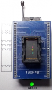
- an universal programmer with a TSOP48 adapter (you can find really cheap adapters on ebay or aliexpress).
The universal programmer is certainly the missing device on your workshop but you might have access to one at the university, at work or at your local electronics shop. You can e-mail me in last resort but you should check the shipping costs to/from France first because it might be more costly than a new device.
05/01/2015:
The whole detailed procedure for desoldering & soldering the chip is now available ->HERE<-.
The second procedure for building a working Flash image and programming it is available ->HERE<-.
.
Please note that the first release of each document (Rev. 05/01/15) shall be considered as a draft. As stated in these documents, any comment or remark is more than welcome. |