TM-241 / TM-441 – Correspondance S-RF et dBm

Ludo | 2 mai 2021


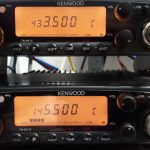
À toutes fins utiles, voici les correspondances entre l’indication des bargraph et le niveau de signal injecté avec le banc radio sur la fiche d’antenne de ces postes. Ces relevés ont été effectués après avoir calibré les S-mètres comme indiqué dans les manuels d’alignement de Kenwood.

TM-241 TM-441
S0: < -123.5dBm
S1: -123.5dBm
S3: -119.3dBm
S5: -114.7dBm
S7: -109.8dBm
S9: -105.7dBm
S9+20: -100.4dBm
S9+40: >-93.6dBm
S0: < -120.9dBm
S1: -120.9dBm
S3: -116.6dBm
S5: -111.7dBm
S7: -107.7dBm
S9: -103.2dBm
S9+20: -98.4dBm
S9+40: >-91.6dBm

Conversion 11F3: mieux vaut tard que jamais

Ludo | 16 janvier 2021
Le monde des radiocommunications est plein de surprises, dont certaines auxquelles on se retrouve confronté à ses dépens. Ce billet fait ainsi suite à la tentative infructueuse d’ouvrir certains relais VHF couvrant pourtant très bien la région dans laquelle je me trouve, et ce même avec presque 100W P.A.R.!. Suspectant un décalage en fréquence du générateur 1750Hz, j’ai connecté mon poste au banc radio, mais ce que j’ai constaté m’a vite aiguillé sur une autre piste.

Lire la suite »

The war is not over!

Ludo | 19 octobre 2012
I just couldn’t stay with so many questions and so few answers, so come check back the protocol descritpion in the next few weeks 😉

I’ve made a scan of the RC-20 Instruction manual, since it’s not available anywhere else, maybe it will be useful to someone.

Trying to find RC-20 commands

Ludo | 23 septembre 2012
Well, I think the protocol description I’ve made is pretty much complete, now it’s time to try every other command than the ones sent by the RC-10 and see what happens (by « see what happens » I mean « pray that the transceiver won’t blow up »). I’ll write a simple program on a Renesas microcontroller that will convert UART frames sent from my computer with Docklight into a synchronous « SPI like » data frame to the TM-241.I’ll try to update this entry ASAP with some test results.

10/07/2012: Well, after trying to use the R8C/25’s integrated USART peripheral for days and a strong headache, I’ve finally capitulated and written a software protocol based on the Timer RA in « Pulse Width Measurement » mode. It uses the clock signal generated by the transceiver to send and receive data. That’s the good news.

The bad news is that the transceiver doesn’t seem to accept any command above 0x3F, so after all this hard work I still don’t know how the RC-20 sends its commands, which is a little bit frustrating.

I did not waste my time anyway since I’ve found the purpose of some other bits from the LCD indicators bit field, but I would have liked to find more about the RC-20…
I’ve updated the protocol specifications with my latest finds.
I’m interested by any information about the operation of the RC-20 (yes, this is an SOS).

First steps…

Ludo | 18 septembre 2012
The LA1034 is now connected to the MIC plug. The communication protocol seems to be SPI, at least that how I’m decoding it with the « Synchronous Serial » interpreter.
The frequency can be easily identified but there are still lots of things to discover:

09/19/2012: One more evening spent playing with the RC-10. I’ve found how to set the TM-241E to correctly send the frequency to the RC-10, but it disables all other informations in the data frame. At least I know my RC-10 is not faulty, the TM-241E seemed to use the RC-20 protocol to send the data out, which caused the erroneous frequency on the RC-10’s LCD.
Now that I have almost all data frames I think I can start to write the protocol specifications. I’ve also found hidden functions on the RC-10. I’ll post all that stuff in a PDF ASAP.
09/21/2012: I’ve finally had some time to write some description of the protocol. This is still a draft though. Protocol Specifications

Just received my RC-10!

Ludo | 17 septembre 2012
Well, I have nothing much to say, excepted that it seems to work, which is a pretty good thing for what I intend to do with it. However, its LCD displays disjointed stuff, like 40.00 all the time, or 40.40, or 40.80 … don’t know why. I can only see the frequencies stored in the transceiver’s memories and call channel, but not the VFO. The VFO data sent by the transceiver seems to be followed by some other data that are mistakenly interpreted as the frequency, so every frequency I set is displayed on the RC-10 then automatically erased with the 40. »something ». This « something » seems to be a bit field that indicates the power level (LOW, MID & HIGH). Anyways, it shouldn’t stop me from hacking it!
Now I have to open the MIC plug and connect the logic analyzer.
To be continued…

First entry….

Ludo | 2 septembre 2012
I’ve been looking for informations about Kenwood’s RC-20 remote control for a long time and I’ve finally stumbled upon this blog recently: http://n9xlc.blogspot.fr/search/label/TM-241a
I’ve never been able to lay hands on one of these remote controls on eBay, mainly because they were too expensive or because the sellers didn’t want to ship it to France. So thanks to this blog I’ve discovered that there was another device that could control my transceivers: the RC-10. I don’t know if they both have the same functions, but I’ve found an RC-10 that I should receive next week and I’ll torture it with my protocol analyzer to hack its protocol too, because I just can’t wait for N9XLC to provide the whole commands list 🙂 Besides the technical challenge, my goal is to be able to build a stand-alone board that would allow me to control my transceivers from anywhere, via an embedded web server for instance. This could lead me to build some kind of repeater controller board… who knows… what do you think about that?