 |
I just couldn’t stay with so many questions and so few answers, so come check back the protocol descritpion in the next few weeks 😉
I’ve made a scan of the RC-20 Instruction manual, since it’s not available anywhere else, maybe it will be useful to someone. |
Hi
It’s a great hack!
I have a TM-541 which is broken display.
So I want to implement this protocol into a microcomputer. 🙂
Thanks.
Hi Jun,
I hope you’ll succeed! There are still some undiscovered LCD indicators in the bit field, like the ALT indicators on the TM-541. Please let me know if you find where they are in the data frame.
I’ve connected the RC-10 and the RC-20 to my TM-241E and my TM-441E, but only the TM-241E allows to control the AF output. I’ll email Kenwood to know if it’s a firmware issue, but unfortunately if it really is, the microcontroller will have to be changed since it’s using mask ROM…
Hi Ludovic,
I’ve implemented data loging program on an Arduino.
The following is a log data of ALT indicators.
0 41 42 49 65 40 40 50 8F # connect to the RIG and send ‘0x00’
2 42 41 40 40 40 80
8 80
0 41 42 49 65 40 40 50 8F # push F
2 42 40 40 40 40 80
7 4F 81
8 81
0 41 42 49 65 40 40 50 8F # push ALT
2 42 41 40 40 40 80
8 80
6 84 # enable ALT
6 86 # left arrow indicating
6 84
6 86
6 84
6 86
6 84
6 86
6 84
6 86
6 84
6 86
6 84
6 86
6 84
0 41 42 49 65 40 40 50 8F # push F
2 42 40 40 40 40 80
7 4F 81
8 81
6 86
6 84
0 41 42 49 65 40 40 50 8F # push ALT
2 42 41 40 40 40 80
8 80
6 80 # disable ALT
It seems to send with 0x06 in ALT indicates.But the right arrow doesn’t indicating. I don’t know how indicate it 🙁
Just to make sure there’s no misunderstanding: did you see the right arrow on the LCD but not on the data frames, or you don’t have it logged because it didn’t not display on the LCD?
I’ll update the protocol specifications with your findings and the frequency data frame, which has an extra byte on your transceiver for indicating the « 1 GHz ».
Thank you for updating protocol specifications !
I tried to receive signals which has a right arrow shift.I checked the 0x06 frame following :
0x06 0x80 # disable ALT
0x06 0x84 # ALT
0x06 0x86 # left arrow + ALT
0x06 0x85 # ALT + right arrow
That’s great! I was waiting for this last command to publish the updated protocol specifications. I’ll do that later this day, when I’ll be back home.
The only missing thing is the DRS indicator. Since I don’t have this optional board fitted on my transceivers, I’ll send « fake » frames with my microcontroller to find this mysterious bit. Then I think we’ll have everything we need to build a RC-20 clone, but without the IF-20 support until I get a chance to buy one, or if someone accepts to help me by placing a communication logger that I will provide, between his RC-20 and IF-20.
Hi
I’m writing RC-20 protocol to serial converter on an Arduino. I think that RC-20 clone will be made if this is used. I will open the source code in few days 😉
Wow, you’re amazingly fast! I’m not really in the mood for coding after a full working day 🙂
I’ve updated the protocol specifications, please let me know if there is something that is not very clear, so I can make it more understandable. I’ve also made room for the IF-20 protocol, but I can’t say more for the moment…
Hi
I’ve just uploaded the source code onto Github. https://github.com/jun930/rcx0_clone
I’ve just wrote an article of TM-541 remote controller.
http://www.geocities.jp/jun930/ham/tm-541.html
You can translate any language with google translate tool top of this page.
Wow, you’ve come a long way in a fairly short time. I haven’t had much time to work on the reverse engineering myself. I think I may try to use your protocol specifications to make a program for a msp430 based board to communicate with my radio. Then if I ever have the time I’ll move on to reverse engineering another radio’s interface. My work using the Launchpad MSP430 boards has only really been in Energia, which is an Arduino clone IDE.. I’d like to teach myself C++ for the microcontrollers using gcc instead, it might be more powerful. 🙂
This work is going to come in handy one day.. I could see it being used for a codec2 addon for these radios. One could build a device that not only did the codec2 encode/decode and modem, but also control the Kenwood TM-xx1 radios in a fairly seamless interface. 🙂 Or perhaps make something just like the Kenwood D710 head unit to add APRS to the radios.
James
This is a really nice job you made with the Arduino board Jun. Thank you for sharing your source code!
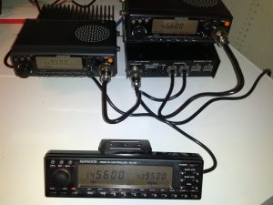
I’m really happy to see you here James. I had nice opportunities to get all these devices for a low price, I just couldn’t miss that! I’ve received the last piece of the puzzle this Saturday:
http://blog.shibby.fr/wp-content/uploads/Images/Radio/KENWOOD/TMxx1/TM-241E_TM-44E_IF-20_RC-20.jpg
Unfortunately I won’t have much time to hack the protocol between the IF-20 and the RC-20 or even just play with it for the upcoming weeks.
For those who might be interested, ON4NYO still has RC-20s for sale: http://www.2ememain.be/radioamateur/produits-nouveaux-commerciaux/autres-articles-nouveau/kenwood-rc20-controller-134824719.html
hi ! sooo long time no see.
I’ve moved blog page to https://jun930.hatenablog.com/entry/2019/06/16/213556 because geocities of Yahoo has been closed.
thank you.
Jun
Hi Jun,
It’s a pleasure to get news from you!
I’ve updated the links to your website in the PDF.