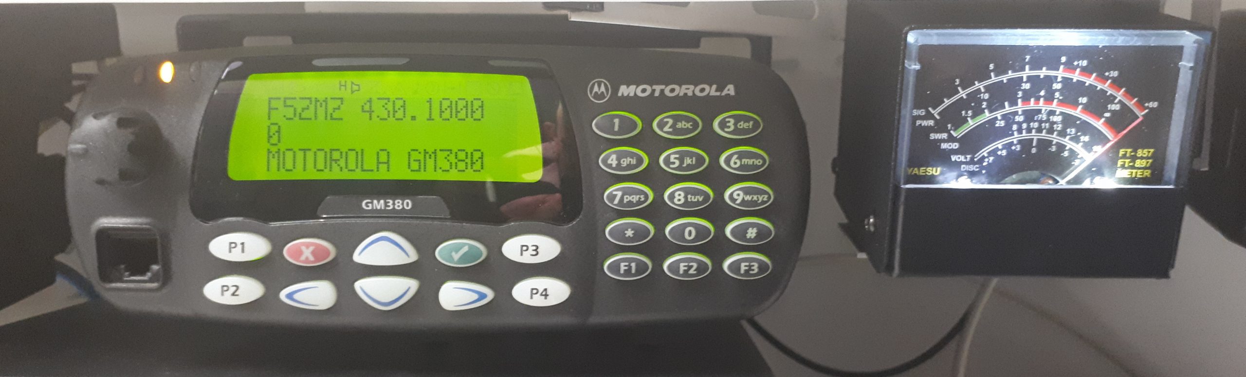
Motorola Waris series S-meter
Ludo | 11 février 2018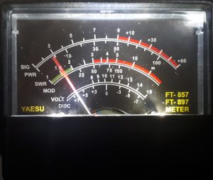 |
Although the following design is not revolutionary at all, it still has the benefit of fulfilling its primary function and bringing back memories of electronics courses about op amps. Moreover, it does not need any specific measuring tool for the calibration process. You’ll need something to generate a strong RX signal though, like your kid’s PMR talkie-walkies, in order to set the full range signal reading. |
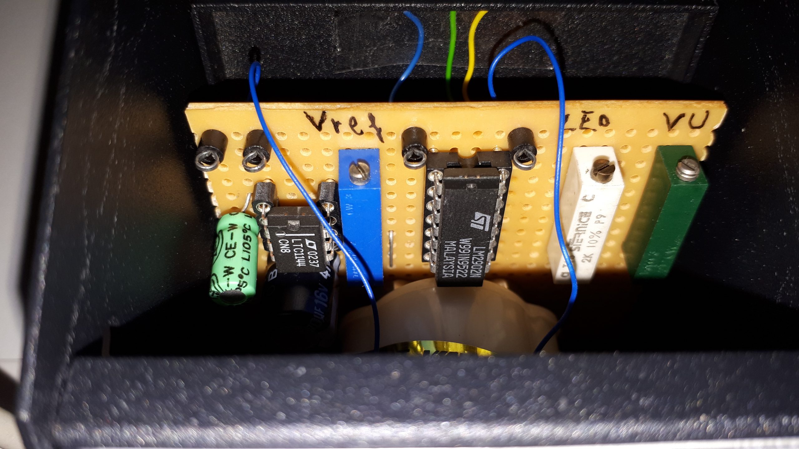
The required voltage adaptation for driving the S-meter could not be easier, since it only consists of a voltage follower, followed by a differential amplifier. The only tricky part is to generate the negative voltage from the +12V provided by the radio, but Linear has some regulated inverting charge pumps ICs that help reducing the bill of materials, like the LTC1144 that you can get as free sample on their website.
Let’s go to the most interesting part of this entry: the schematic.
Well, as mentioned above, I did not reinvent the wheel. This design can absolutely be used on any other transceiver as long as its RSSI voltage output does not exceed the op amps power supply itself, which should always be the case. There is also no reason for it not to work with other parts than the LM2904. D3 avoids negative voltage to be applied to the positive contact of the vu-meter.
So, here is how to get it working:
- Make sure RV1 is set to its higher value before switching the transceiver on ;
- Connect a dummy load or just disconnect the antenna and make sure you don’t transmit ;
- Switch the transceiver on and adjust RV3 in order to obtain 0 Volt on U1B pin 7 ;
- Connect the antenna and use an other transceiver to transmit on the current receiving frequency ;
- Adjust RV1 until the s-meter’s needle reaches the max value ;
- Stop transmitting with the other transceiver.
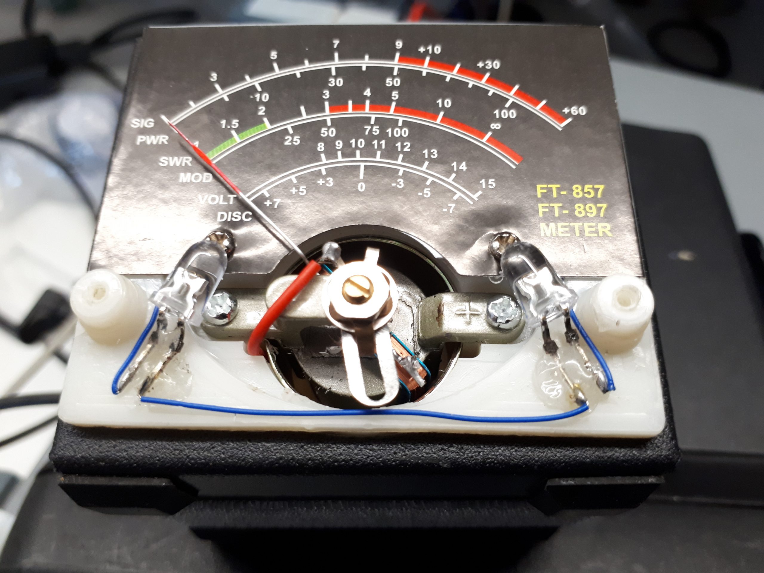
The LEDs shown in the schematic are used to illuminate the scale. I placed them at the bottom of the needle because illuminating it from behind was not an option. The two white LEDs are held with hot glue. I drilled two thin holes in a non visible area in order to get their power supply going through the vu-meter.
I did not take any picture of the whole assembly before putting everything back together, so you’ll have to imagine a little bit what was done from the following pictures. I’ll reopen the box to take more detailed pictures later…

The S-meter I use is one of those: https://www.aliexpress.com/wholesale?catId=0&initiative_id=SB_20180211100037&SearchText=external+s+meter


